 Hit Reload if you don't see motor image
The motor was then ignited on a static test stand to measure thrust. This is a spring weight scale. The static burn is videotaped and the thrust over time is plotted by analyzing each frame for thrust. The video captures 30 frames per second.
The sim results are obtained by entering the chamber and grain data into the Excel file and solving for output.
I did not graph the ends=1 sim for this motor as this was the last page I wrote and it was clear that two ends (ends=0) or one end (ends=0.5) needed to be inhibited in the Sim. (And I was sick of plotting ;-)
Once these graphs are available they are roughly compared for maximum thrust, burn time, and if the thrust curve is
neutral, progressive, or regressive.
Any obvious differences in the sim file are addressed by changing input into the SRM.xls file.
Of course the input changes need to reflect reality so the focus is changes that reflect the non-standard
construction of these grains.
Results
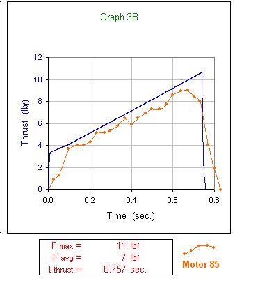
From the graph below it is seen that the static data is a progressive burn. I did not plot this against the neutral SRM sim where ends=1.
The graph below shows the static data against the SRM with ends=0 The value for grain length (L0) is the average of the two core lengths. Then N=2
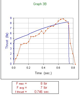
Replotting the static data against the SRM workaround with ends=0.5 (L0=core lengths averaged and N=2) gives the following graph:
Conclusions
The curve in this motor's static data is as progressive as is the sim with ends=0.
This is a different than the other motors checked in this process.
Looking at the area under the curves suggests that the Sim with ends=0.5 is more accurate as far as total impulse is concerned.
The SRM with ends=0 gives this a total impulse of 22.7 NS calling it an E30.
The SRM with ends-0.5 gives this a total impulse of 22.0 NS calling it an E29
Engedit gives the static data a total impulse of 19.99 NS so it is a high end D. calling it a D25)
(A tiny touch more thrust in one Engedit data point and I'd have an E25 ;-)
Note that the longer core in the delay grain makes this a D25 whereas the sustainer version with the shorter core in the delay grain tested as a D19
To further test this process one could try a variety of motor/grain configurations to see if these workarounds
keep the predictive value of SRM.
See the results for:
The one grain motor
The standard "two" grain motor
The two grain booster motor ...That link is this page
The two full grain motor
The three grain motor
Another question is the reproducibility of these small motors. Too much variation in performance would make all this
"fine tuning" of the sims a mute point. The one grain page listed above includes 2 static motors side by side.
Click Here to see a preliminary comparison of four standard "two" grain motor statics.
Back to Drysophila-Sorbitol Project Main Page

::: Made with CoffeeCup : Web Design Software & Website Hosting :::